|
Efficiency of DC-DC Converter
|
|
4. Efficiency of DC-DC Converter
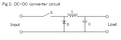
EVs and HEVs are equipped with 12-V parts of ordinary gasoline-engine vehicles as an auxiliary power source.On the other hand, they@generally employ step-down DCDC converters to cope with high-voltage high-output power requirement for a drive power source.Recently a study concerning utilization of the DC-DC converter as a vehicle drive power source has been initiated to cope with charging a drive power source battery for FCVs. It aims at compatibility of vehicle performance and mounting space in the vehicle by adopting a high voltage motor, thus allowing for greater design freedom in the drive motor. Additionally it aims to reduce costs by decreasing the number of cells (voltage on the battery side is lowered).However, this will cause a loss of power efficiency by several percent points (%) and also result in an increase in the number of parts. Therefore, vehicle weight reduction, optimum layout, and cost reduction must be studied before adopting the DC-DC converter. The following explains the efficiency of
the step-up/-down functions of a DC-DC converter that serves as a drive power source.
On the assumption that the DC-DC converter is to be applied to the drive system, it is important to create a design by which loss of energy is minimized even if the maximum output is high.
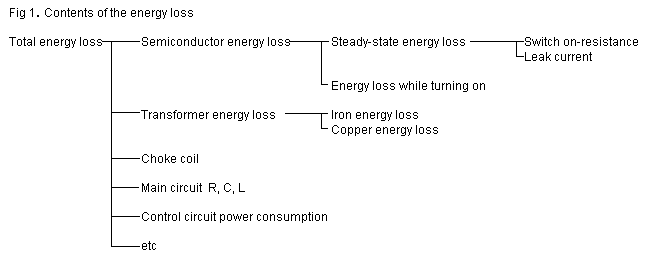
Energy loss of the DC-DC converter is classified as shown in Fig.1.Each of these items will be explained as follows.


1. Energy loss of semiconductor -- Steady state energy loss
Semiconductors produce low resistance during switching while they are being energized. When the switch on-resistance is Ron and the output current comes to Ion, energy loss expressed by Ion2 * Ron is constantly generated. Furthermore, small amount of current flows even when the semiconductors are not being energized. When the leak current is Il and the operating voltage is Vz, energy loss expressed by I1 * Vz is generated.
When the output is high, Ion is also great; thus, Ion2 * Ron accounts for the majority. In the standby mode, Ion becomes 0; thus, there is only Il * Vz.
Semiconductor material characteristics depends the operating voltage and output.Assuming that the material is the same, the higher the voltage resistance is, the greater the switch on-resistance becomes. The reason for changing the rectifier circuit from a pn-junction-type diode to MOSFET or SBD is to reduce switch on-resistance.
With commercialization of SiC for semiconductor material in the future, it will lead to significant effects.
2. Energy loss of semiconductor during switching
Energy loss occurred during switching is time integration of the product of switching voltage and current.
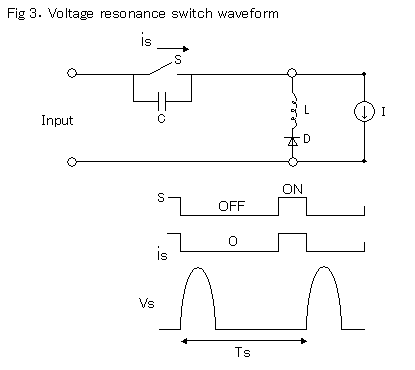
Therefore, reduction of the switching time (use of a high-speed switching element) decreases the amount of energy loss. Providing control to maintain the voltage or current applied to the switch at zero during switching for dynamic control of the voltage/current waveform can also reduce the amount of energy loss.Various types of resonance-type converters and ZVS-PWM converters are being developed according to this principle.

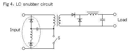
Switching operations also produce a surge voltage or surge current, resulting in a significant effect on voltage resistance and noise. Zero-voltage switching is effective to suppress surge during turning the switch on. Various snubber circuits were used as measured against surge while turning on. In recent years, switching control has been used to suppress surges, eliminating snubber circuits.

3. Transformer and choke coil energy losses can be categorized into energy losses of copper and iron.
Because there are significant restrictions on weight, costs and capacity for on-board application, a high frequency switching which allows for downsizing of coil is applied.Since the switching energy loss increases at high frequencies, generally a frequency range of 100 to 200 kHz is applied to MOSFET, and 10 to 20 kHz is applied to IGBT.
Since iron energy loss in a coil is caused by magnetic hysteresis, loss is greater at high frequencies. In addition, reduction of unit size decreases the thermal capacity and heat radiating surface area; therefore, critical heat resistance is decreased.
Copper energy loss depends on coil wire diameter and the number of turns.The minimum wire diameter is determined according to the coil characteristics and output, and frequency and coil specifications are determined while increasing the number of coils so that the total energy losses of copper and iron is at a minimum. In this process, the iron core size is normally reduced to a level at which the amount of energy loss increases at magnetic saturation point.
Amorphous magnetic cores with small magnetic hysteresis used in utility power applications begins to saturate at about 1 tesla, and this makes it difficult to realize downsizing. Additionally, there is significant disadvantage for costs and vibration level, which is considered not be suitable for application to automobiles.
The instantaneous maximum output requirement for use in vehicles is 5 to 10 times greater than steady state conditions. Therefore, it is important to set operating conditions to ensure efficiency.
4. Other assumed causes of energy loss are small in absolute value. They are negligible, except in continuous low-output operation.
In conclusion, it is reasonable to say that the performance of the DC-DC converter depends on the material development technology of semiconductor, magnetic material and switching control technology. However, accurate setting of operating conditions for vehicles is also important to increase efficiency and to cope with downsizing.
|
|