2. Estimation of the upper limit capacity of an electric double layer capacitor
Will the capacity of the capacitor exceed that of a lithium-ion battery?
What are the future trends concerning the use of capacitors and lithium-ion batteries?
Due to recent performance improvements of the electric double layer capacitor, application to FCV and power assist for commercial vehicles has begun. Points for expanded application in the future to estimate size and cost that will increase as capacity is increased taking technological advances into consideration.
First of all, one advantage of the capacitor is low internal resistance and high durability when handling a large current. Thus, it is theoretically possible to design a system in which peak power is decreased and system costs are reduced by the power supply. In the application to a system in which a battery is used as the primary electric power source, it is conceivable to eventually develop a low cost, low output, and high capacity battery.
When using a battery to store electricity, the most important characteristic features are either rapid charging or a system in which there is an inputthat is significantly lowerthan the output.
However, since the cost of capacitor system is substantial, an assessment of cost is important when applied to a system in which the cost of a large power source is not so high compared toa FCV or to the development of an exclusive use engine.
Since a single cell that can withstand the voltage of the capacitor is approx. 3V, the way the capacitor system is usually used is for there to be many cells that are connected in a series with an equally controlling voltage for each cell at approx.
2.5 V to 1.0V by providing a DC-DC converter for both charging and recharging systems.
Here let me estimate the upper limit capacity of an electric double layer capacitor according to this principle.
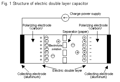
An electric double layer is formed by applying an electric field to an electrolytic solution. Ions in the electrolytic solution separate and are drawn to either the positive or the negative electrode. When this phenomenon occurs, positive ions (such as Li+) are drawn to the negative electrode (such as carbon) and aligned.

Take a look at this. There are free electrons on the negative electrode. Why are positive ions not combined with these electrons and why do not they deposit metal? The reason is believed to be something along these lines. A certain degree of energy is required for an ion to get an electron and the voltage is applied.
If voltage is increased further in the case of a Li-ion battery, intercalation in which ions are inserted into carbon crystal occurs but in the case of an electric double layer capacitor, ions are just aligned.
Since ions carry an electric charge, the upper limit of the capacity can be estimated by counting the number of ions in the electrolytic solution. Organic solvent dissolves by approx. 1 mol of lithium salt per liter. 1 mol of 1-valent ion corresponds to approx. 100K coulomb.
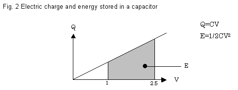
If a capacitor containing 1 liter of electrolytic solution is fully charged up to 2.5V, in other words, to an electric charge of 100K coulomb and if it is discharged to 1.0V, and then discharged again, the electric charge would be 60K coulomb because Q = CV and Q2.5 = 100K = 2.5C as shown in Fig. 2, Q1.0 = 1.0C and Q2.5 ? Q1.0 = 60K coulomb.

The discharged electric charge is calculated as 60K coulomb = 60KAs = 16.7Ah.
Since the mean voltage during discharge is (2.5 + 1.0)/2 = 1.75V, energy capacity is 16.7 x 1.75 = 29.2Wh.
Using these numbers, the performance of a capacitor system will be approximated.
Assuming that the upper limit of the electrolytic solution volume for installation in an ordinary vehicle is 100 liter, and if 100 cell capacitors each one of which contains 1 liter of electrolytic solution are connected in series and they separate between 250V and 100V, then the upper limit capacity would be 2.92 KWh.
Rounding the figure to 3 KWh allow us to estimate the size of the system.
Since the volume of the electrolytic solution is 100 liter, and the electrodes, cell container, control circuit, DC-DC converter and relays are added, the total volume would be 150 liter and the weight would be 200kg.
Accordingly it would be assumed that the critical capacity of a system application in the future is 500 liter in volume and 70Kg in weight per KWh.
The system cost would be, estimating for volume production;
Electrolytic solution: 2,000 yen/ liter x 100 liter = 200K yen
Electrode and separator: 250K yen
Control circuit: 100K yen
Packaging: 50K yen
DC-DC converter: 100K yen
If the costs of assembly, administration and transportation are approx. 50% of the above total,
The cost of the system would be about 1.05 million yen.
The future target would be 350,000 yen per KWh.

There are many technological tasks such as the development of electrolytic salts (multi-valence and high solubility), as well as stable electrolyte solution for higher voltage, the addition of a reservoir for electrolyte solution and an increase in electrode surface area. Accordingly, estimating the costs of the system is not easy.
In conclusion, the use of a battery is currently suitable for a vehicle whose useful life is comparatively short. I believe that the capacitor system is more suitable for items such as a standby power type power supply, route delivery use which use recharging stations, electric train, bus and industrial machinery.
|