| The control system and the inverter of the AC motor |
|
PWM inverter (three-phase voltage control type)
The inverters generate the three-phase AC from a DC power source such as the battery of the electric vehicle, which is required to drive the induction motor or the synchronous motor.
When the electric vehicle is driven, the motor torque should be controlled according to the rotating speed and the driver's intentions.
The inverter driving the AC motor needs to have a function to change the voltage, current, and frequency of the AC in order to control the torque and the rotating speed.
Of the various types of inverters available, the three-phase voltage control type PWM inverter is most commonly used in electric vehicles.
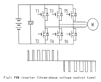
Figure 1 shows the circuit of this type of inverter. The high-capacity condenser and the three sets of two power devices in series are connected to the DC power source in parallel. And the three-phase power is taken out from the center of these two power devices.
To generate the AC power from the DC power resource, the inverter controls the switching devices' on-off time duration for changing the output voltage, and selects the combinations for changing the polarity. These alternate combinations of on-off transistors are limited to the eight sets shown in Table 2.
The inverter may choose these combinations sequentially. The function of the large electrolysis capacitor in the voltage control PWM circuit is to compensate the voltage drop at the timing of the transistor on-off actuation, and to keep the DC voltage constant. Therefore, the inverter can change the output voltage quickly according to the on-off time duration without spiking.


Reference
Book title: EV Handbook
Written by: EV Handbook Publisher's Group
Published by: Maruzen Co., Ltd. (URL http://www.maruzen.co.jp)
|
|